| .vscode | ||
| 3d | ||
| firmware | ||
| pic | ||
| tools | ||
| .gitattributes | ||
| .gitignore | ||
| lp3ctrl.sh | ||
| README.md | ||
This project is based on: https://github.com/mariusmotea/diyHue/tree/master/Lights/Arduino/Generic_Dimmable_Light
So this firmware is also able to be used the same way like a diyHue.com device.
Reef2Reef forum thread: https://www.reef2reef.com/threads/for-lumini-lominie-pixie-30-p30-hers-how-to-add-ramp-up-down-and-timer-with-memory-quite-cheaply.935409/
Most of the code was generated by ChatGPT and adapted by myself.
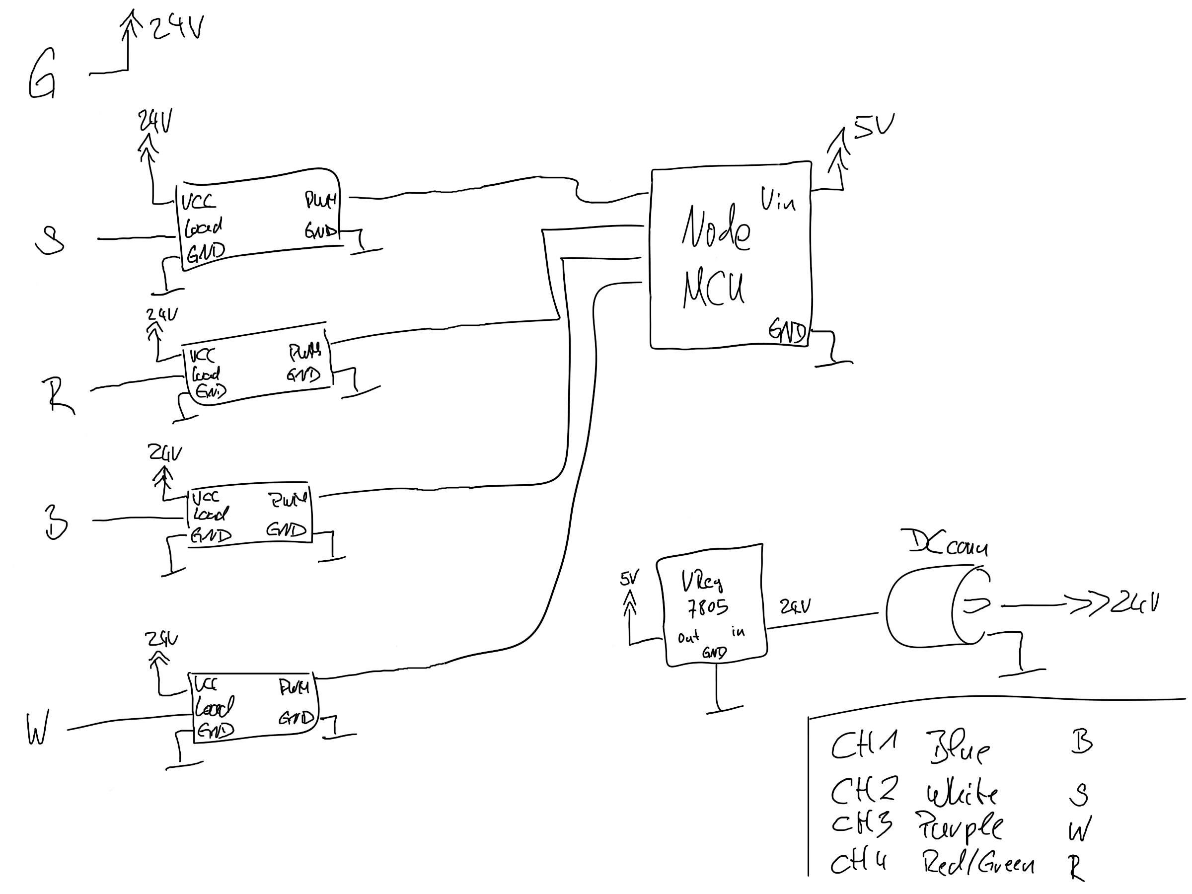
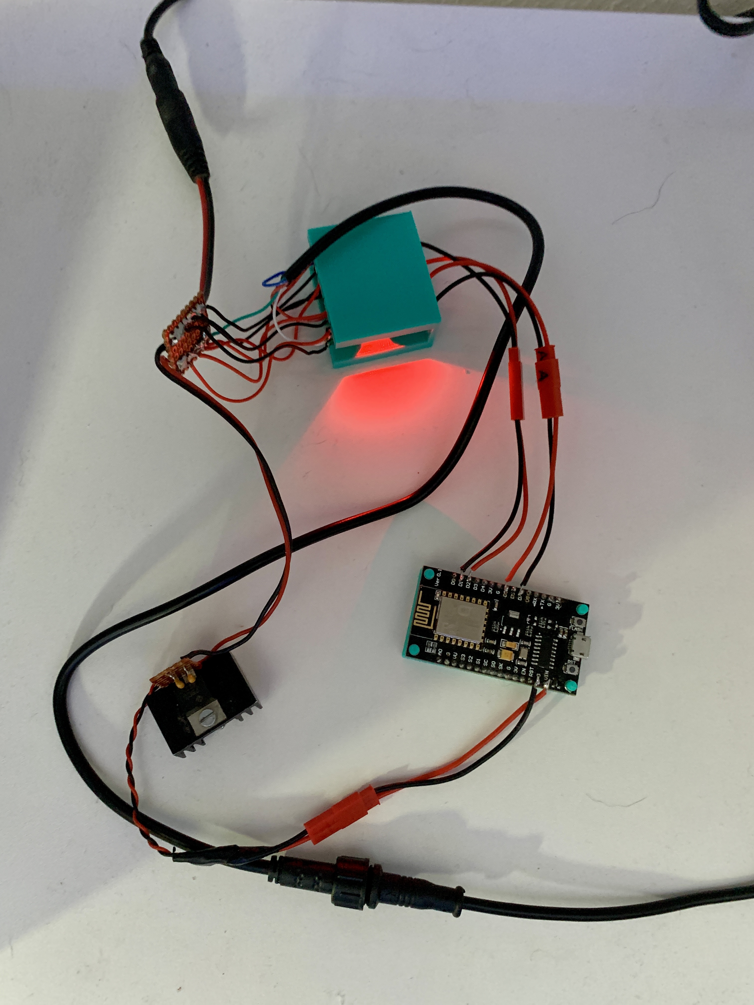
The controller I use is a old NodeMCU v1.0, which is connected to 4x D4184 MOS breakout boards. See NodeMCU pins table beyond. The cable I use is a https://amzn.eu/d/0jigRCh. I cut it in half and attached it to the MOS boards.
The NodeMCU‘s power supply is a 7805, it‘s output is connected to the Vin pin of the NodeMCU. The input of the 7805 is connected to the 24V of the DC power plug.
NodeMCU pin connections to the cable wires:
| ch1 | ch2 | ch3 | ch4 | |
|---|---|---|---|---|
| LED color | blue | warm white | purple | white & red & green |
| Wire color | blue | black | red | white |
| Arduino pin names | D1 | D2 | D7 | D5 |
| GPIO | 5 | 4 | 13 | 14 |
The HTML content is pushed to the NodeMCU separetely by using the ESP8266 Sketch Data Upload plugin of the old Arduino IDE (not "Arduino IDE").
After the firmware is written the first time to the NodeMCU.
In case there is no data folder available in the firmware folder create it. Open a unix style commandline with a bash and step unto the data folder. Run the script
$ bash ../../tools/html_gen_files.sh
This generates all of the required files and places them into the data folder.
The EEPROM's default values are set to default. All except of the timing control data block.
You have to click at the link "reset timing control data" on the webinterface.
The IP address is set to dynamic (DHCP) after initial flash of the NodeMCU.
Sample schematics (no NodeMCU pins defined in there)